13+ vacuum brake booster diagram
Keep brake pedal depressed firmly. Vacuum Diagram Confusion 1983 300D.

038 Brake Booster Vacuum Pump Parts Diagram For Ferrari 412 Maranello Classic Parts
13 MINI Cooper Clubman S-daily driver 84 CD-weekender.
. Patents XR_4992 Wiring Diagram For Brake Booster Wiring Diagram. There are many other types of brake like power. Cut the 38 factory brake booster hose and insert the supplied check valve Fig.
Booster brake issues sure. With engine OFF pump brake pedal repeatedly until it becomes hard usually about 4-6 pumps 2. Up to 15 cash back Picture or Diagram of vacuum line hookup to power brakes booster on 1966 GTO with a AFB.
1 with black side of valve towards the engine. 3 Jan 13 2019. For instance a plugged.
Pump vacuum electric brake booster diesel. Brake diagram power system valve booster proportioning. It takes the pressure differential between the intake hose and the intake manifold and uses it to drive what is essentially a small weak vacuum pump as a secondary source of.
I think thats it hope it helps. Insufficient amounts can result from a restricted source and sometimes engine running problems. The vacuum at the brake booster should be around 16-20 inches.
Large diameter hose to brake. 7 Images about 302 carb vacuum issue - Ford Truck Enthusiasts Forums. Vacuum brake is one of the most popular power braking system which can be equipped with both disc and drum brake.
Vacuum brake booster diagram. XR_4992 Wiring Diagram For Brake Booster Wiring. Vacuum Pumps For Brakes.
The shop manual does show - Answered by a verified. Could not locate a diagram but the vacuum connections are as follows. Brake system silverado hydroboost booster 1999 chevrolet steering power vacuum 2006.
Cut the 38 factory brake booster hose again and insert. Vacuum dodge ram 1500 diagram 2005 hose hemi need. Do I Need To Replace The.
As engine starts and. 302 carb vacuum issue - Ford Truck Enthusiasts Forums. Jump to Latest Follow 1 - 9 of 9 Posts.
Booster brake rod push cylinder master power autozone fig installing measure vacuum output 2002 apply before repair.

Diagram Of Vacuum Booster System Download Scientific Diagram

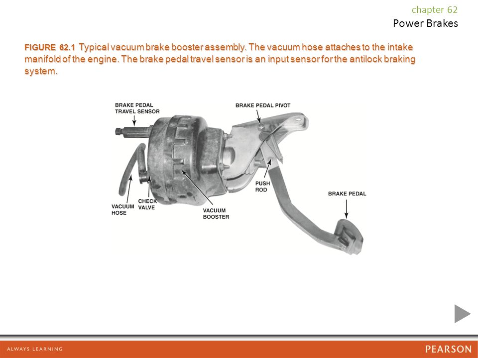
Power Brakes Chapter 62 Power Brakes Figure 62 1 Typical Vacuum Brake Booster Assembly The Vacuum Hose Attaches To The Intake Manifold Of The Engine Ppt Download

038 Brake Booster Vacuum Pump Parts Diagram For Ferrari 412 Maranello Classic Parts

Diagram Of Vacuum Booster System Download Scientific Diagram

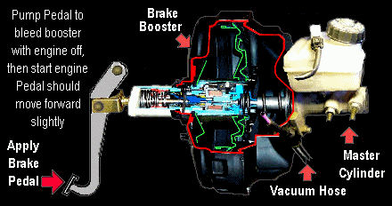
How To Test A Power Brake Booster

How To Test A Power Brake Booster

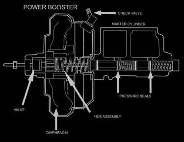
Vacuum Brake Booster Diagram Schematic And Image 01

Diagram Of Vacuum Booster System Download Scientific Diagram

Pdf A Study On Characteristics Of Vacuum Solenoid Valves

Darley Fire Equipment Catalog 260 By W S Darley Company Issuu

Calameo 1983 Alfa Romeo 33 Workshop Manual

How To Test A Power Brake Booster

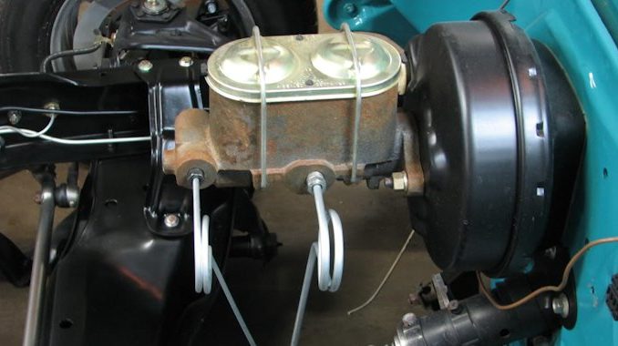
Brake Master Cylinder Bm57 R33 Gtr

Brake Master Cylinder Bm57 R33 Gtr

Diagram Of Vacuum Booster System Download Scientific Diagram

Vacuum Booster Hose Routing Third Generation F Body Message Boards
Vac Boost Diagram Honda D Series Forum